CNEX / INFRASTRUCTURE FIELD GUIDE
NVIDIA GB300 NVL72 Power Plant Deployment Guide
From rack-scale architecture to facility readiness. A technical blueprint for deploying Blackwell Ultra inside an operating power plant.
By CNEX / Enterprise Infrastructure
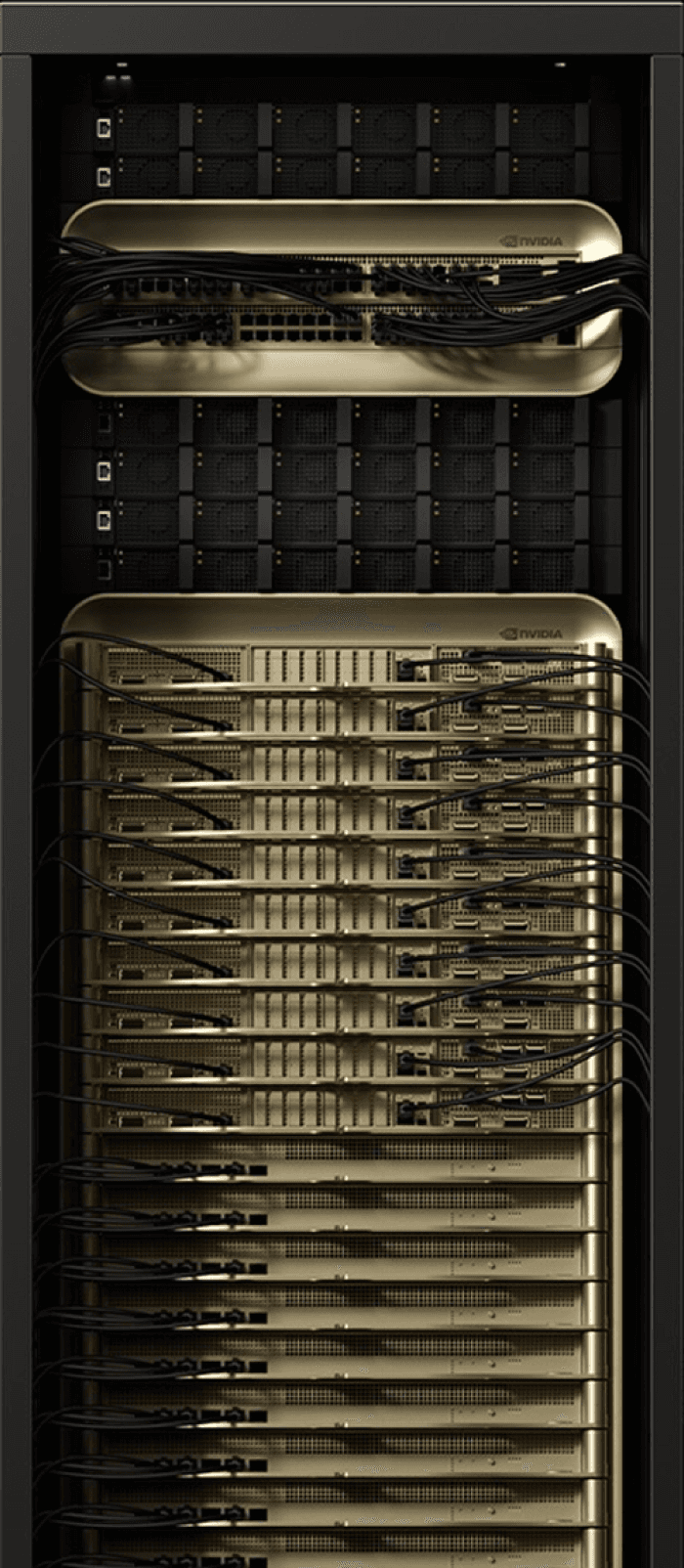
ENGINEERED FOR THE PLANT
One rack. A new class of AI infrastructure.
Scope the complete system—not just the GPUs. Align compute, power, cooling, and operations before deployment.
72-GPU architecture and NVLink fabric
Power delivery and liquid-cooling readiness
OT integration and workload migration
01 / SYSTEM ARCHITECTURE
What is GB300 NVL72?
One rack. 72 GPUs. Acting as a single massive accelerator. Blackwell Ultra GPUs and Grace CPUs are connected by fifth-generation NVLink in a fully liquid-cooled, rack-scale system.
72 GPUs
Compute tray
18 compute trays integrate 72 Blackwell Ultra GPUs. Each tray combines four GPUs and two Grace CPUs.
Compute trays
18
GPUs per tray
4
Cooling
Cold plates
36 CPUs
Grace CPU
The CPU layer orchestrates data movement and connects the GPU complex to system memory.
CPU architecture
Arm
Cores total
2,592
CPUs per tray
2
~120 kW
Rack power
Power shelves feed the rack through a DC busbar. Plan the complete electrical and thermal envelope.
Power delivery
48 V DC
Facility supply
3-phase
Design basis
OEM-specific
02 / SPECS DEEP DIVE
Compute, memory, and fabric.
The architecture is designed for large-model inference and reasoning. Figures below follow the reference’s planning envelope; precision, configuration, and OEM implementation matter.
NVFP4
Compute
Blackwell Ultra brings native low-precision acceleration to demanding AI workloads.
Architecture
Blackwell Ultra
GPU count
72
FP4 per GPU*
~15 PFLOPS
Execution
Tensor Cores
HBM3e
Memory
High-bandwidth memory keeps larger model weights and active contexts close to compute.
HBM per GPU
288 GB
HBM total
~20 TB
GPU bandwidth
~8 TB/s
Memory stack
12-high
NVLINK 5
Fabric
A single NVLink domain reduces cross-device communication bottlenecks.
NVLink per GPU
1.8 TB/s
Rack bandwidth
~130 TB/s
NVLink domain
72 GPUs
Scale-out
ConnectX-8
03 / WHY IT MATTERS
Four reasons to bring AI inside the plant.
Power generation creates complex, sensitive, real-time data. Local compute places model execution closer to the systems and people that need it.
01 / MODEL CAPACITY
Plant-scale language models
Bring operating procedures, maintenance histories, P&IDs, and OEM documentation into a private knowledge environment. Large memory capacity supports demanding model deployments.
02 / SIMULATION
Real-time digital twins
Connect simulation and visual models with live plant data. High-bandwidth GPU communication supports complex, multi-model digital-twin pipelines.
03 / OPERATIONAL CONTEXT
Reasoning for operations
Investigate trips, alarms, and maintenance patterns with reasoning workflows. Keep operator review and plant safety controls separate from AI recommendations.
04 / DATA CONTROL
Sovereignty by design
Keep sensitive operational data within the site security perimeter. Apply access control, audit logging, and an approved OT/IT integration boundary.
04 / POWER PLANT TOPOLOGY
Four zones. One controlled data path.
Place the rack in a dedicated AI infrastructure room. Separate plant control, data aggregation, compute, and operator-facing applications with explicit trust boundaries.
OT DATA SOURCES
Zone 1 — Plant floor
DCS controllers • PLC cabinets • Vibration and thermal sensors • Edge modules
Interface / OPC UA / Industrial Ethernet
Boundary / Approved read-only extraction
CONTROLLED TRANSFER
Zone 2 — Data aggregation
Plant historian • Time-series buffer • DMZ firewall • OT/IT bridge
Transport / Private, encrypted link
Governance / Audit-logged data access
RACK-SCALE COMPUTE
Zone 3 — AI infrastructure
GB300 NVL72 rack • CDU • Switchgear • Scale-out fabric • Model registry
Facility envelope / ~120 kW rack planning basis
Cooling / Dedicated liquid loop
HUMAN-IN-THE-LOOP
Zone 4 — Applications & operations
Plant LLM console • Digital twin viewer • Reasoning workspace • Operations dashboards
Serving / Triton inference workflows
Control / Operator approval retained
05 / POWER & COOLING
120 kW per rack changes the facility equation.
This is not a standard server-room installation. Coordinate electrical capacity, heat rejection, structural loading, and service access as one engineering package.
ELECTRICAL
Power delivery
Validate upstream capacity, protection, redundancy, and the complete OEM power-shelf configuration.
Rack draw* / ~120 kW
Supply basis* / 480 V, 3-phase
Rack busbar* / 48 V DC
THERMAL
Liquid cooling
Direct-to-chip cooling requires a commissioned secondary loop and a facility heat-rejection strategy.
Cooling method / Direct liquid
CDU planning* / 150–200 kW
Acceptance / Flow / pressure / leak test
STRUCTURAL
Physical footprint
Survey the delivery route and structural design before the rack arrives. Preserve maintenance clearances.
Cabinet mass* / ~1.36 tonnes
Floor loading* / ~440 psf
Access / Front and rear service
CONNECTIVITY
Network fabric
Engineer scale-out connectivity alongside the OT boundary, management network, and storage paths.
NIC class* / 800 Gb/s
InfiniBand / Quantum-X800
Ethernet / Spectrum-X
06 / WORKLOADS
What runs on the rack.
Map each workload to a measurable operational objective. Consolidate inference where appropriate, then validate isolation, latency, and capacity under representative load.
01
Plant foundation LLM
Search procedures, maintenance records, incident reports, and OEM manuals in natural language. Ground answers in approved site documentation.
PRIVATE KNOWLEDGE
02
Real-time digital twin
Combine simulation and plant telemetry to explore equipment behaviour, visualise conditions, and evaluate operational scenarios.
SIMULATION
03
Reasoning agent
Investigate operational events using historical context and structured evidence. Present recommendations for engineer review.
DECISION SUPPORT
04
Multi-modal plant vision
Process thermal imagery, inspection footage, and acoustic signals to support detection of equipment anomalies.
VISION + LANGUAGE
05
Heat-rate optimisation
Serve combustion, vibration, and emissions models alongside one another. Test recommendations against site operating constraints.
MULTI-MODEL INFERENCE
06
Synthetic data & training
Use available capacity for fine-tuning and simulation-generated datasets. Track model lineage and promote through controlled releases.
MLOPS
07 / HARDWARE COMPARISON
From Hopper to Blackwell Ultra.
Compare system classes—not just GPU generations. HGX figures describe an 8-GPU node; NVL72 figures describe a complete 72-GPU rack.
Specification
H200 / HGX 8-GPU
B200 / HGX 8-GPU
GB200 NVL72
GB300 NVL72
Architecture
Hopper
Blackwell
Blackwell
Blackwell Ultra
GPUs per system
8
8
72
72
HBM per GPU
141 GB HBM3e
192 GB HBM3e
192 GB HBM3e
288 GB HBM3e
Total HBM*
~1.13 TB
~1.5 TB
~13.4 TB
~20 TB
NVLink per GPU
900 GB/s
1.8 TB/s
1.8 TB/s
1.8 TB/s
NVLink domain
8 GPUs
8 GPUs
72 GPUs
72 GPUs
Power envelope*
~10 kW / node
~14 kW / node
~120 kW / rack
~120 kW / rack
Cooling*
Air / rear-door HX
Air / liquid
Direct liquid
Direct liquid
Primary fit
Existing AI workloads
Enterprise AI nodes
Rack-scale AI
Large-scale reasoning
* Indicative reference figures, not a final engineering specification. Confirm performance precision, electrical supply, CDU sizing, floor loading, and cooling conditions with the selected OEM and qualified site engineers before procurement.
08 / DEPLOYMENT PATH
A phased path from survey to production.
An illustrative 16-week programme—not a delivery commitment. Procurement, permitting, utility readiness, and site acceptance determine the actual schedule.
WEEKS 1–3
Survey & design
Review floor loading, electrical capacity, coolant conditions, network routes, and OT integration. Agree the site acceptance criteria.
WEEKS 4–6
Facility preparation
Prepare switchgear, CDU placement, manifold runs, containment, and the approved network boundary.
WEEKS 7–12
Rack & platform integration
Position and commission the rack. Validate cooling, fabric, storage, model registry, and inference services.
WEEKS 13–16
Workload migration & handover
Benchmark priority workloads, rehearse recovery, train operators, and complete production acceptance.
09 / ENGINEERING FAQ
Before you commit to rack-scale AI.
Common questions for infrastructure, operations, and procurement teams.
SIZING
Do we need NVL72, or is an 8-GPU system enough?
Start with model size, concurrency, latency, and growth requirements. A smaller system may suit bounded workloads; NVL72 addresses larger scale-up domains and demanding multi-model deployments.
FACILITY
Can an existing IT room handle the rack?
Do not assume it can. Confirm available power, cooling-water conditions, floor loading, delivery access, and service clearances through a site engineering assessment.
COOLING
Is liquid cooling mandatory?
GB300 NVL72 is a liquid-cooled rack-scale platform. Plan the CDU, secondary loop, water quality, leak detection, and facility-side heat rejection together.
MIGRATION
What does migration from H200 involve?
Validate the software stack and model performance on the target platform. The larger change is often at the facility layer: power, cooling, networking, commissioning, and operational readiness.
START WITH SITE READINESS
Plan your plant’s next generation of compute.
Bring your plant layout, electrical capacity, and cooling-water specifications. Define what fits today, what needs to change, and a practical deployment path with CNEX.
Blackwell Ultra GPUs
Total HBM3e
NVLink fabric
Rack planning envelope